
documentation


In the prior article, we've made familiar with VisionLib Configuration files and introduced some of the parameters needed to set for tracking to work correctly – either manually in a text editor, or by using VisLab (which is recommended).
For better understanding, we distinguish between tracking parameters to influence the computer vision tracking, and parameters you need to configure, each time you setup a configuration to track a new object.
Initial parameters typically change per new configuration, whenever you are going to track a new object. You need to setup these parameters in the tracker.parameters {} element to get tracking started, and declare at least:
modelURI or models[]metricinitPoseSetting these will enable VisionLib to generate a so called Line Model, which is essential information used by the image processing during the tracking process.
| Name | Description | Examples |
|---|---|---|
modelURI | URI to your 3D file used as tracking reference | Relative to the .vl file: "modelURI": "project-dir:/my3Dmodel.obj" |
models | Alternative to modelURI: enables to load multiple 3D models as tracking reference, which are combined and treated as one single reference Line Model representation | "models":[ {"name":"Part1", "uri":"project-dir:/car-exterior.obj","enabled":"true" }, {"name":"Part2", "uri":"project-dir:/car-interior-.obj","enabled":"true" }] |
metric important | Sets the corresponding unit size of your model in metric scales (e.g mm, ft, m). This is an essential parameter which tremendously influences tracking quality | "metric": "m" |
initPose | Describes the initial pose or viewing angle, from which tracking should start. Essential for standard Model Tracking (excluding AutoInit and MultiModel Tracking setups) | "initPose": "t": [ x, y, z ], "q": [ x, y, z, w] } |
Using modelURI is rather straight-forward, and it is the very basic way to define the tracking target's reference by pointing to the corresponding 3D model used as reference.
There are other, more advanced ways to load 3D files for tracking, such as:
"models":[...] – uses an array, where a tracking target can be composed of multiple 3D files. These multiple files, however, will be treated like one single tracking reference, basically declared by (sub-)parts (it should not to be confused with Multi Model Tracking).TrackingModel to use Unity Hierarchy objects for tracking, which doesn't need a config file definition at all. Instead, the 3D meshes are handed over to VisionLib during runtime.Have a look at the example scenes at VisionLib Examples/Model Tracking/ModelLoading within the VisionLib.SDK.Examples-Unity.unitypackage for demos on how to load 3D models for tracking.
The metric parameter is essential, if not critical to get well working tracking results and it has to be set appropriately.
It tells VisionLib the corresponding measurement of your 3D model and puts the relative units of it into a measurable size – which is the basis to derive the Line Model information for tracking.
So, with metric you define in which metric scale your model was created and how it should be measured, i.e. whether the numerical size of your mesh represents mm, cm, m or another metric.
To give an example: Say the (bounding box) dimensions of your 3D model read for instance:
When you set the Metric parameter in the config file to "m" (i.e. meters), VisionLib will interpret this as a 32 meters large object – and consequently expects your physical object to be of that size. Because the numbers then read:
If your object was only 32 centimeters large, however, you would need to change Metric to "cm" (i.e. centimeters) instead. Then it would read:
By simply changing the metric parameter, the same numerical values of your 3D file lead to different size interpretations. That is the desired effect. That's the desired effect.
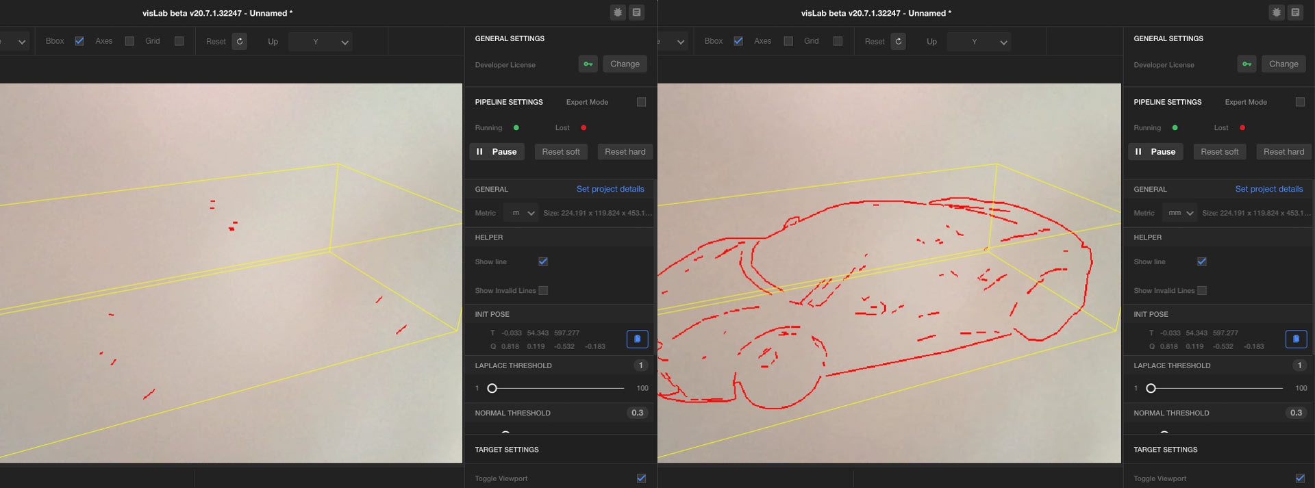
Liked stated above, the metric simply puts the numerical units into a measurable scale. Say, you have 15 centimeter large object and a 3D model with mesh dimensions around 152.0 units, but you set metric to "m"(meters). As VisionLib would interpret this as an 152 meter large object, looking at the line model would make it appear coarse and inappropriate for tracking a physical object, that's only around 15.2 centimeters large. Putting it back to "mm" leads to better results. The image above illustrates this (left: non-fitting metric, right: appropriate metric).
If metric isn't set, VisionLib will use mm by default and interpret all given mesh dimensions like millimeter-scaled models.
While VisionLib can handle several metrics, we generally recommend to create all meshes in a meter-scaled metric. When combining VisionLib tracking with external SLAM (ARKit, ARCore, or HoloLens), the metric must be declared in meters, as these system make it mandatory.
If your 3D model is not in the right scale, please re-scale it in your 3D modeling software before using it as tracking reference. Don't correct the scale of the tracking reference model by scaling it in Unity, as VisionLib will not be aware of this transformation.
To turn the first example above into a meter-based scale, we would need to re-scale the mesh by factor 100, and then set metric from cm to "m":
In doing so, we've simply express the same dimension in another metric without changing the actual size, because our (physical) object is still 32 centimeters large. Here, 1 (numerical) unit expresses 1 meter (and values below 1 are less than a meter).
Unity is metric-free. As such, it doesn't enforce any units and can work with any metric. However many of Unity's built-in modules calculate in meters as well, and treat one unit as one meter. An object with the dimensions 1 x 1 x 1 would then be a meters-sized cube:
If you are not sure about your model’s metric, use VisLab, or a 3D viewer such as MeshLab. Here, you can measure the length of the 3D model or its bounding box and draw conclusions on unit and scale.
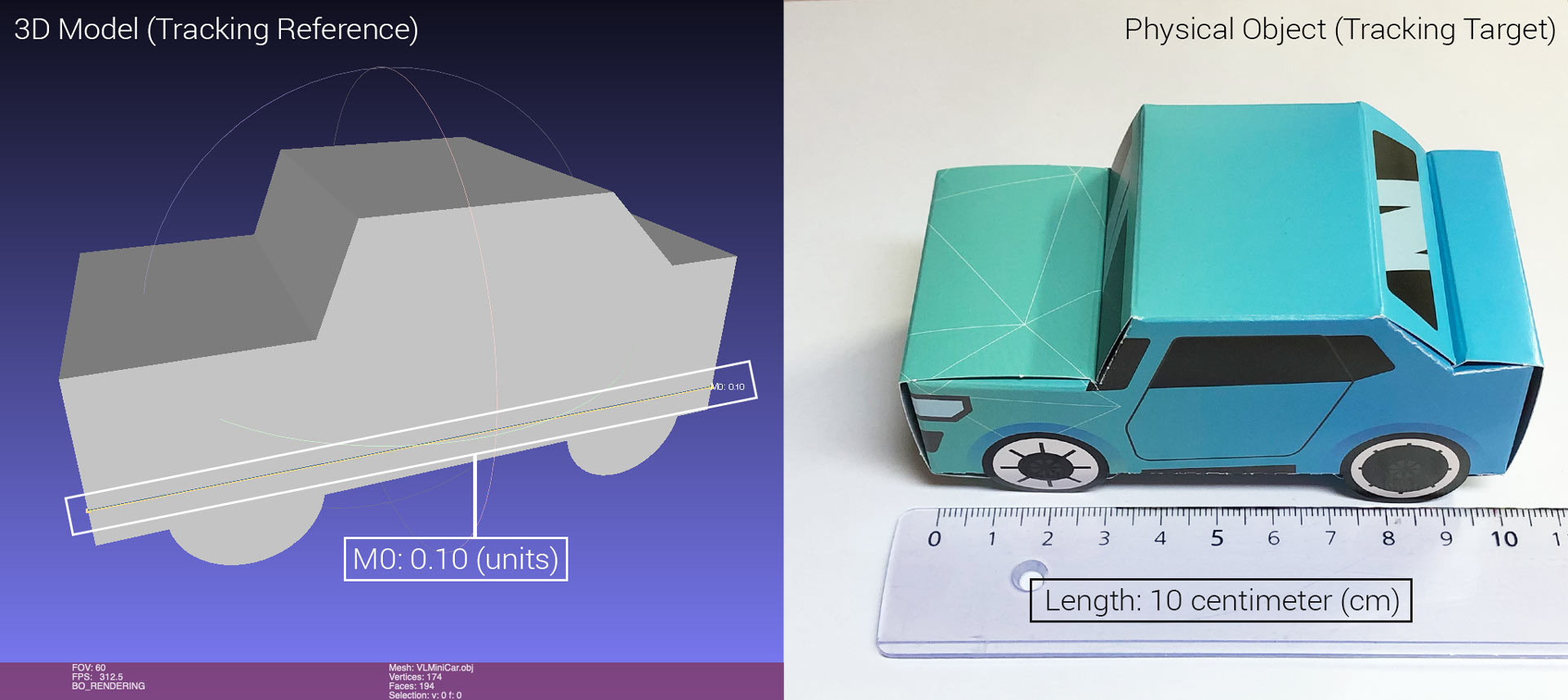
Let's take the VisionLib Mini Car do-it-yourself test object as an example (download foldsheet & obj-file from our Resources page or get it from our Unity example scenes):
The length of our physical do-it-yourself test target is 10 cm. Measuring the dimensions of the corresponding .obj file in Meshlab shows 0.1 units, i.e. it has the desired size. How to read this result? Well, as we'd like to express an meter-scaled metric, 1 unit represents 1 meter. As such, the result reads that this model represents a 10 centimeter-sized object in a meter's scale.
VisionLib since 20.6.1 also issues warnings, if it finds your 3D file's bounding box is of implausible scale, which often indicates mismatching metric or scale errors.
When you import 3D model used for tracking to put it into the Unity Hierarchy in order to augment it onto itself, always check, whether your metric fits in Unity after importing tracking reference models for visualization purposes.
You can not simply re-scale a metric within Unity, because it would create a mismatch between the 3D model used for visualization and the one used as reference for the tracking. Make sure, that the Unity Model Importer doesn't change the scale of the model.
Such cases often lead to errors, which are hard to find, because it might happen that your 3D scene is too large or too small to be seen at runtime. As a result, the augmentation might simply not show up, although tracking works fine and fits configuration-wise.
The initPose describes the initial view position and orientation (pose) to get tracking started. If it isn't set upfront in the configuration file, it won't stop your Unity project from running; at least, when the VLInitCamera prefab is present. Having neither will basically never lead to tracking results, when using standard Model Tracking (i.e. not using Auto-Init), because VisionLib misses this essential information to initially detect and match your object from that pose.
The initPose should be adapted each time you change the tracking target. You can do this inside Unity by modifying the VLInitCamera GameObject or use VisLab to set the init pose while you configure the configuration file there.
A tutorial and detailed background on init poses is given in this article.