documentation


The majority of AR tracking techniques use a collection of computer vision and image processing methods for tracking. VisionLib is no difference and it has a set of tracking parameters to control and influence the behavior of these underlying methods to some degree.
This article focuses on essential (but optional) tracking parameters to influence the tracking results of VisionLib's Model Tracking: They either affect the so called Line Model creation, or the image processing, in which objects are detected & tracked in the video stream.
Usually, modifying these parameters is not necessary. This article helps understanding them and explains how they affect the tracking.
Tracking parameters are part of the tracker.parameters {} element of configuration files. A full overview on parameters for Model Tracking, including the here covered parameters, is given at the Model Tracker Reference page.
By modifying tracking parameters listed here, one can influence the tracking quality and optimize it in cases, when tracking isn't working as expected.
We give control to these parameters, because enterprise AR cases can be complex, and an "one-fits-all" tracking configuration might not always lead to satisfying results.
Usually, the default values of the tracking parameters work fine. These defaults are listed in the full Model Tracker Reference and used e.g. in VisionLib's Unity SDK example scenes.
Before changing the tracking parameters, we encourage to test the defaults first. We recommend to use VisLab to explore their influence on tracking. In Unity, you can modify some of them via the example UI of the Advanced Model Tracking example scene.
For debugging purposes, set debugLevel: 1 and showLineModel:true in your config file in order to see then influence on the Line Model at runtime. More strategies on Debugging are given here.
In a prior article we discussed the mandatory parameters to get tracking started and to enable VisionLib to generate the Line Model from this configuration. The Line is important, because its so called search lines, are used to detect and track the real objects as seen in the video stream. Those are especially relevant during initialization.
The tracking parameters allow you to modify and refine this line model and the image processing of the tracking process.
For the sake of understanding, we've split up them into basic and advanced ones. If you run into cases, where you need to make changes to them, start modifying the basic ones first. Usually there are only very few (edge) cases, where you need to modify the advanced ones at all.
Further below we debrief all parameters in detail. That said, please note that we give only a general introduction here. For a full technical reference, lookup the Model Tracking Reference.
| API Name | Descriptive Name | Category | Unit |
|---|---|---|---|
| laplaceThreshold | contour edge threshold | edge generation | mm |
| normalThreshold | crease edge threshold | edge generation | 0.0 - 8.0 |
| minInlierRatioInit | detection threshold | pose estimation | 0.0 - 1.0 |
| minInlierRatioTracking | tracking threshold | pose estimation | 0.0 - 1.0 |
The four parameters above are the first ones to look at if you experience that tracking works somehow, but results don't appear satisfying.
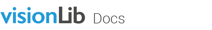
Generally speaking, modifying the laplaceThreshold influences rather the (outer) contour edges of your object, because it basically controls the depth jump in space to be interpreted as an edge and ergo influences the depth sensitivity.
The example image above shows a configured laplaceThreshold of 1, 5 and 10 mm for a 1:18 car model of a Ferrari (with normalThreshold at a very high value to render it irrelevant).
The amount of inlying lines decreases. Subsequently, there will be less search lines during tracking to detect depth-related structures of the physical model; so tracking will be less sensitive in using these.
Note, that the Metric parameter (introduced in a prior article) has strong influence on all parameters we debrief here, but it especially affects the laplaceThreshold, which influences the Line Model generation. We recommend to ensure it's set appropriately before looking into laplaceThreshold and normalThreshold).
This threshold modifies line generation for neighboring surfaces and the angle between them. As such, it has influence on crease or curvature edges of your model.
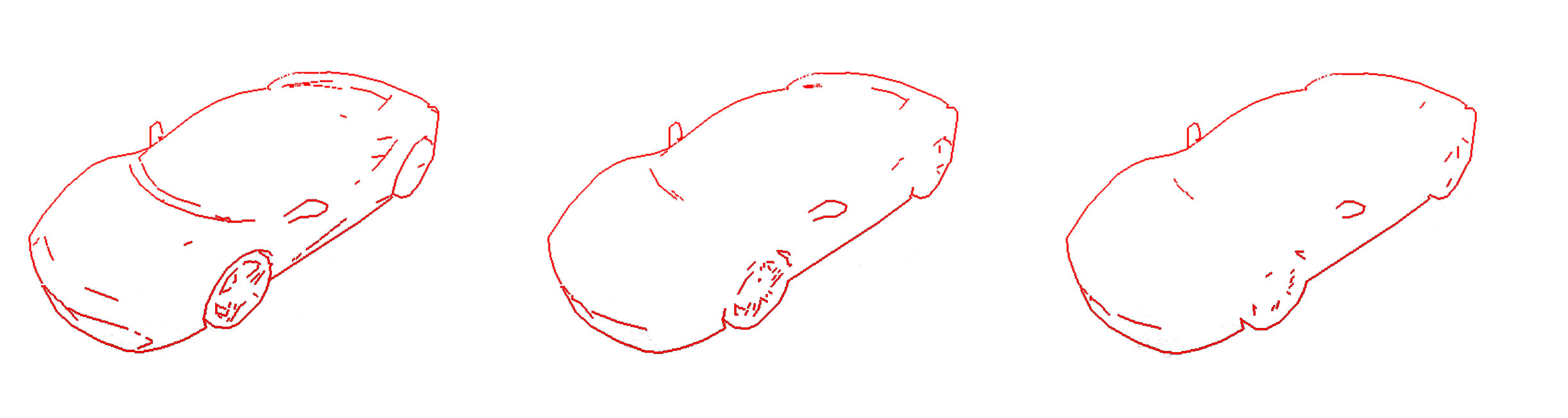
The example image shows different normalThreshold settings: 0.01, 0.1 and 0.4 (where laplaceThreshold is 1). You can see, that it rather influences inner edges.
Compared to laplaceThreshold, the normalThreshold is less relevant and, if set too small, it may result in generating non-detectable lines and in bad performance. You can disable it by setting it to a very high value, if it has bad influence in your case.
However, for objects with significant crease edges, it might be of use optimizing the normalThreshold parameter.
While minInlierRatioInit influences the detection sensitivity (i.e. the threshold, at which model tracking snaps at initialization), minInlierRatioTracking influences tracking sensitivity (i.e. the threshold until continuous tracking breaks).
Have a look at the (default) settings from the minicar.vl which is used by the Unity example scenes:
Both parameters are connected, and refer to the tracking quality. Actually, if you look at the quality indicator in visLab's debug view, you can see, it ranges in the same value continuum.
The minInlierRatioInit threshold would ideally be 1.0, meaning that for detection we'd get a 100% match between the Line Model and the physical object as seen in the video stream. In reality, however, this is hardly reached due to different influence factors.
As a rule of thumb we can say that:
minInlierRatioInit should always be a little higher than minInlierRatioTracking. Good values to start with is a pair of: 0.6 and 0.5minInlierRatioInit too high, means it'll be very strict and tracking won't initializeminInlierRatioInit is too low, it'll be more tolerant or fuzzier and tracking might initialize sooner, but it probably snaps and tracks false geometric structuresBefore modifying the minInlierRatio* parameters, you should first modify parameters affecting the line model generation (i.e. laplaceThreshold and normalThreshold).
To conclude, both thresholds depict the ratio between found and not found parts of edges: so a high value means that a lot of the edges could be found in the actual camera image – but as mentioned, making the tracking result rather strict. This won't guarantee that tracking is working better. A single line of an edge of a model might result in a high inlier ratio but will not lead to a significant stable pose estimation. It is always good to have lines in different 3D directions in your camera image for determining a good camera pose.
| API Name | Descriptive Name | Category | Unit |
|---|---|---|---|
| lineGradientThreshold | contrast threshold | edge detection | 0 - 765 |
| lineSearchLengthInitRelative | detection radius | edge detection | 0.0 - 0.5 |
| lineSearchLengthTrackingRelative | tracking radius | edge detection | 0.0 - 0.5 |
| keyFrameDistance | key frame distance | edge generation | mm |
As the descriptive name contrast threshold indicates, with lineGradientThreshold you can influence the contrast sensitivity of edges detected in the video stream along the generated line model. This is a threshold, which works on a pixel basis for all "edge candidates" before they will be included in tracking.
High values will only consider pixels with high contrast as candidates. Low values will also consider other pixels. However, this is a trade-off. If there are too many candidates, the algorithm might choose the wrong pixels. If there are not enough candidates, the line-model might not stick to the object in the image and tracking might break sooner.
Lower this value, if the image is too dark or the image's contrast is too low. White points along the search line's orthogonal line indicate this tolerance. Ideally, there's always only one point, and its placed at an edge, where real object's edge is expected.
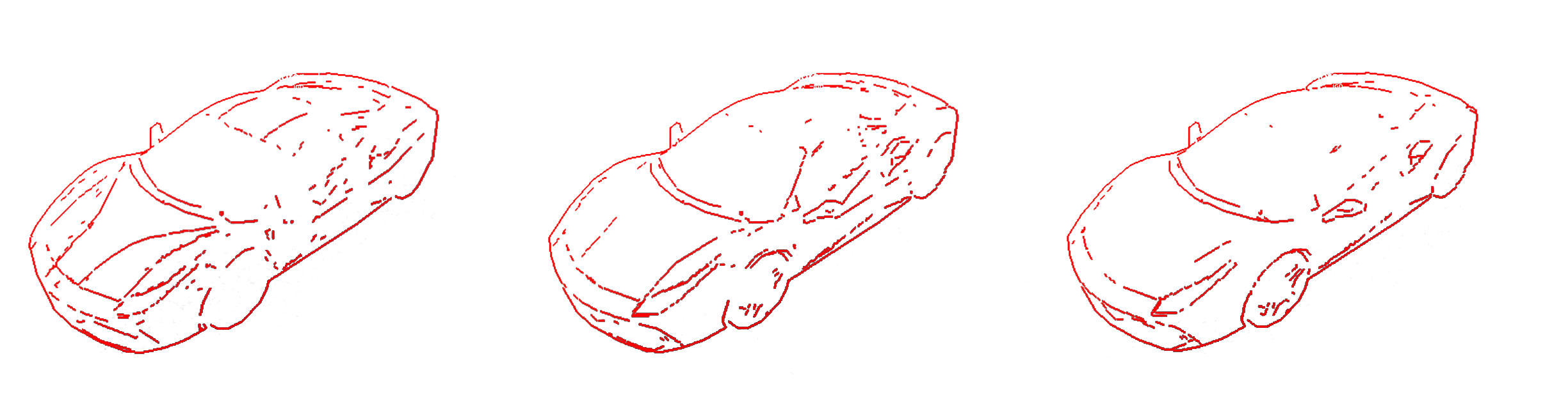
In order to detect and match the generated edges with the ones visible in the video stream, you can specify the tolerance in form of a "length to be searched at" as a relative value. This is an orthogonal area to each line of the line model. You can influence the length of the search lines by setting the lineSearchLengthInitRelative and lineSearchLengthTrackingRelative parameters.
From our experience the default values are fine. Anyway, if you experience a poor initialization behavior, or you expect a more tolerant one, you may increase the lineSearchLengthInitRelative value slightly.
For example: Say you wanted to track a black car in front of you. In a situation with bright daylight you might receive hard shadow edges on the ground. As a result, it might happen that the shadow contour is detected as the object's outer edge, instead of the real one. By lowering the search line's length, you can lower the area where pixels are accounted to be part of the object in such a case.
If by modification the search lines become too short, the initialization seems harder to accomplish, because one has to match the (init) pose very precisely to initialize tracking.
If you tend to loose tracking because the movement between two frames is larger then covered by the search lines, you should increase lineSearchLengthTrackingRelative.
Note: In order to see the search lines in the debug visualization, set debugLevel to 1. Find more on Debugging in this article .
During runtime, so called keyframes are created at a certain distance to each other.
Keyframes have two functions:
The keyframeDistance parameter sets the minimum distance to all other keyframes, after which a new keyframe will be created. For example: A value of 50 (mm) means that a new keyframe is generated every 5 cm.
Be aware that the keyframe distance parameter is always interpreted as millimeters, even if you have set a different metric.
A frequent update of the line model is important, if you are tracking objects with curved surfaces, since the line model represents their silhouettes only for limited perspectives. If the line model deviates too far from the silhouettes in the camera image, you should decrease the keyframeDistance.
Modifying this parameter also affects how many new re-initialization poses will be generated at runtime. If re-initialization takes too long, you should also decrease the keyframeDistance.
Ideally, you would always set keyframeDistance as low as possible. However, since creating a keyframe is computationally intensive, doing it too often might impact the frame rate of the tracking.
Details on how you can use and influence (re-) initalization is also given in this article.
This is the last article in this section. Now you should be all set for VisionLib's (advanced) Model Tracking functions.
Next, we recommend to continue reading the detail articles in › Tracking Essentials. Or, start an own project by following our › Unity Tutorials.