Level: Basic
General
It is crucial to calibrate the user's camera to obtain great tracking results. Therefore, the VisionLib SDK includes a camera calibration pipeline that lets you embed a calibration process into your application.
Not all cameras/devices are supported by default. Especially for desktop and android devices. Therefore, you need to calibrate them to get a good tracking result for your software on these systems.
States of the Camera Calibration Pipeline
The current version of the calibration pipeline can be represented by a simple state machine, which is depicted in Figure_1:
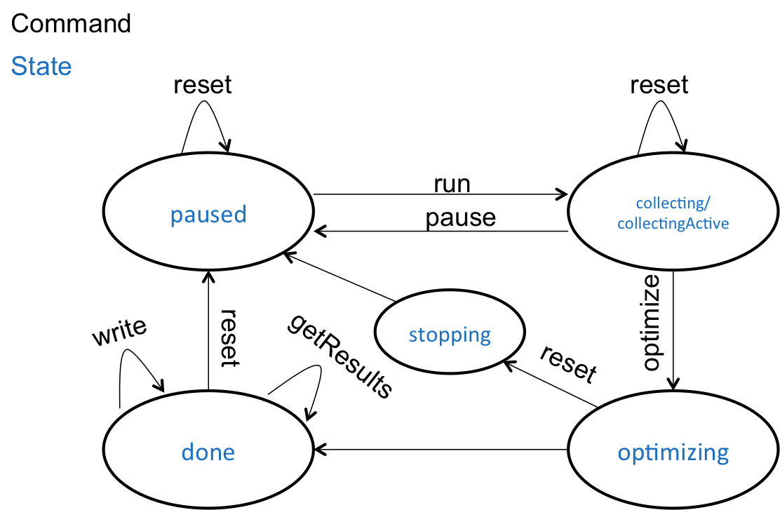
Figure_1: State transitions during calibration
The calibration pipe usually starts in the pause state. By setting the calibration state, the pipeline switches to collecting. Your can switch in between pause and collecting back and forth. When the collecting state is active, a chessboard will be searched with the used camera actively. If the chessboard pattern is found, it will be collected and the _numTemplates parameter of the tracking states will be increased. The state changes to collectingActive when the chessboard is found. You need a certain amount of camera positions collected from different positions in relation to the pattern to get good calibration results (see below). You can reset the collection to restart the process while collecting frames.
After you've collected enough frames (e.g. >100) you can initiate the calibration optimization by issuing the optimize command. The state will transit to optimizing. It can take a while, depending on your device and the number of images collected. You can break the process by issuing a reset or stop command. In this case, the state changes to stopping until the optimization process is really stopped. The state then switches to pause for a clean restart. If a calibration has transitioned to the done state, you may issue the write command along with an URI that in turn will write a proper file with a JSON structure. The calibration will be appended to the existing file, if a certain file already exists. The destinated JSON file is embedded into an array [], which can be treated as a database and loaded through the vlWorker_AddCameraCalibrationDB function in the SDK.
The callback function you passed sends the command getResults and returns a JSON containing the result of the calibration. It has the following format:
{
"type":"vlSDKCameraCalibration",
"version":1,
"timestamp":0,
"organization":"Organization",
"deviceID":"iPad93_BackCamera",
"cameraName":"...",
"calibrated":true,
"intrinsicsDist":{... camera calibration with distortion ...},
"intrinsics":{... camera calibration without distortion ...},
"alternativeDeviceIDs":[... a list of alternative deviceID strings ...]
}
You can notice that two camera calibrations are saved. The user can choose between using the tracking with or without distortion, if the calibration is used. On mobile devices, the cameras are usually pre-calibrated and the default value (uncalibrated) is used.
One calibration consists of the following parameters:
{
"width":640, // Horizontal resolution
"height":480, // Vertical Resolution
"fx":1.2, // Horizontal normalized focal length
"fy":0.8, // Vertical normalized focal length
"cx":0.5, // Normalized principal point
"cy":0.5,
"k1":0, // k1-k5 = radial distorsion parameters
"k2":0,
"k3":0,
"k4":0,
"k5":0,
"s":0, // Skew
"calibrationError":0.25, // calibration error in pixels
"quality":"awesome" | "fine" | "ok" | "poor" | "failed" // human readable
}
You can download the chessboard here. It generally looks like this:
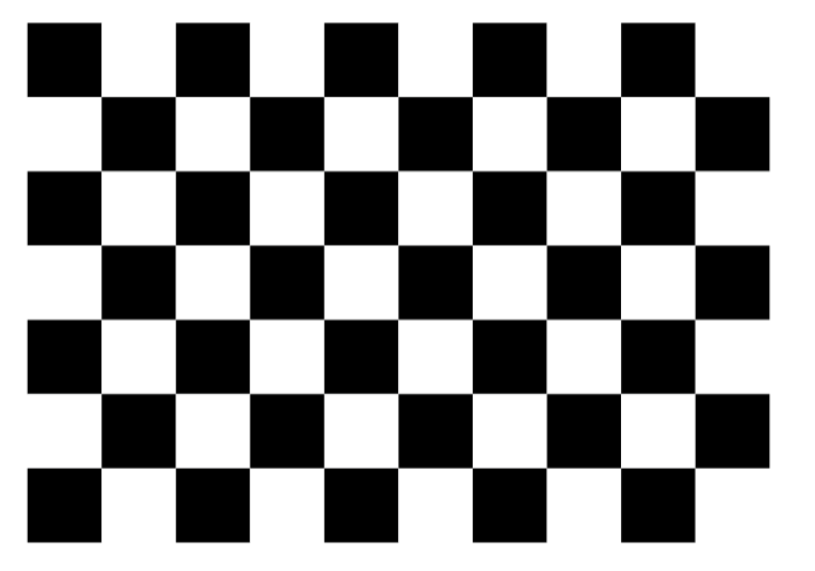
Figure_2: Chessboard pattern
Using the written Camera Calibration Database
You can use the camera calibration database in your unity project. For now, you can add an uri to it using the vlWorker_AddCameraCalibrationDB or AddCameraCalibrationDB of the VLWorkerBehaviour in Unity. You should call this function before you initialize a new tracking configuration. The function loads and merges the database with the internal one when loading the configuration. In case of merge errors, this is pointed out in the tracking initialization issues.
You can also configure the URI using the Camera Data Base URI property in the VLWorkerBehaviour (CamCalibConfig).
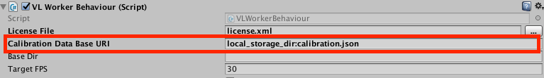
Figure: Using the Camera calibration database
Configuration File Parameters
Currently no parameters are needed for setting up the calibration pipe.
You can use the image recorder parameters for logging the image sequence. In this case, the image recorder is turned off by default.
The following parameters can be set inside the image recorder configuration file:
| Parameter | Type | Default value | Example |
| calibrateOnStartup | bool | optional (false) | "calibrateOnStartup": true |
| Will start the the pipe in the calibration state, when the pipe starts running. |
Example Configuration File
{
"type": "VisionLibTrackerConfig",
"version": 1,
"meta": {
"name": "Simple Recording Example",
"description": "Simple configuration file allowing for recording image sequences",
"author": "Fraunhofer IGD"
},
"tracker": {
"type": "cameraCalibration",
"version": 1,
"parameters": {
}
}
}
Using Scheme Parameters
You can pass the camera as a cameraID with a parameter: input.useDeviceID=YourCam. Or even more abstract: input.useCameraPosition=back.
The system will always try to find the best camera for your needs.
Recommendations for obtaining accurate and reproducible calibration parameter estimates
Currently, the calibration pipeline is unguided so that the user has a very large amount of freedom in choosing the calibration setup and the camera path during recording. However, the quality of the calibration strongly depends on the input of the user. Therefore, the following summarizes some aspects that should help to obtain accurate and reproducible calibration parameter estimates.
The user should consider the following recommendations for the calibration setup:
-
Equal horizontal and vertical square side length: You can print the calibration pattern for camera calibration on paper to any size. For the intrinsic calibration of individual cameras it is not necessary to know the absolute width (for example in mm) of the chessboard squares. However, it is important that the chessboard squares are exactly the same length horizontally and vertically after printing. The best way to validate it, is to measure the width and height of several adjacent squares rather than just one.
-
Rigid and planar calibration surface: After the chessboard pattern has been printed on paper, it should be attached to a rigid, non-deformable object with a perfectly planar surface. We recommend the use of spray adhesives, which achieve the best result to create an even surface. Please beware that attaching the paper with adhesive tape, usually curls the paper, which can lead to measurable errors during calibration.
-
Visualization on flat screen: We recommend you to visualize the chessboard on a standard flat screen of a desktop computer instead of printing it out. Usually, side-length chessboard squares of the displayed pdf version are maintained very well and the planarity of the calibration body is ensured.
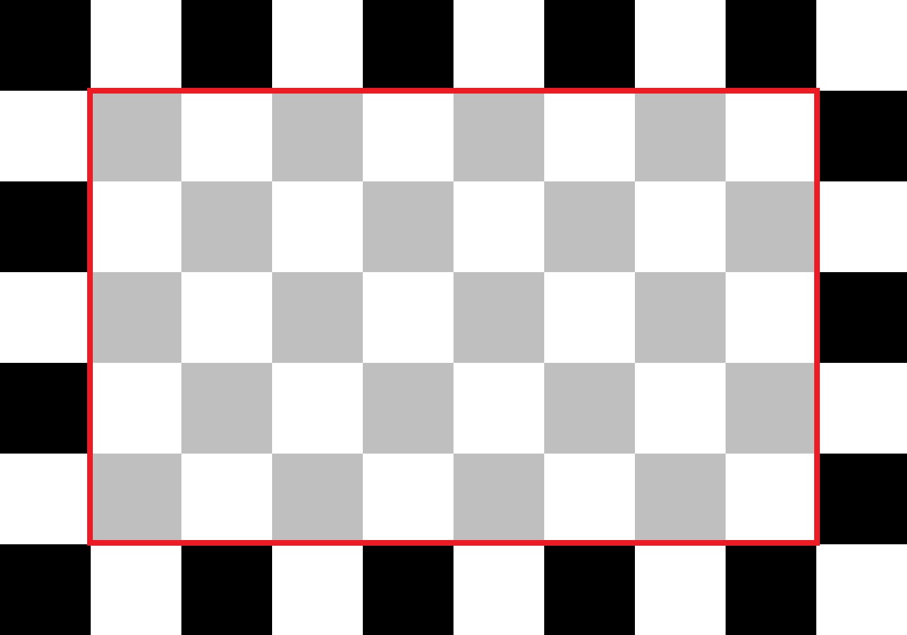
Figure_3: Relevant area of the chessboard pattern. This area must be completely visible in an image so that the chessboard can be successfully detected.
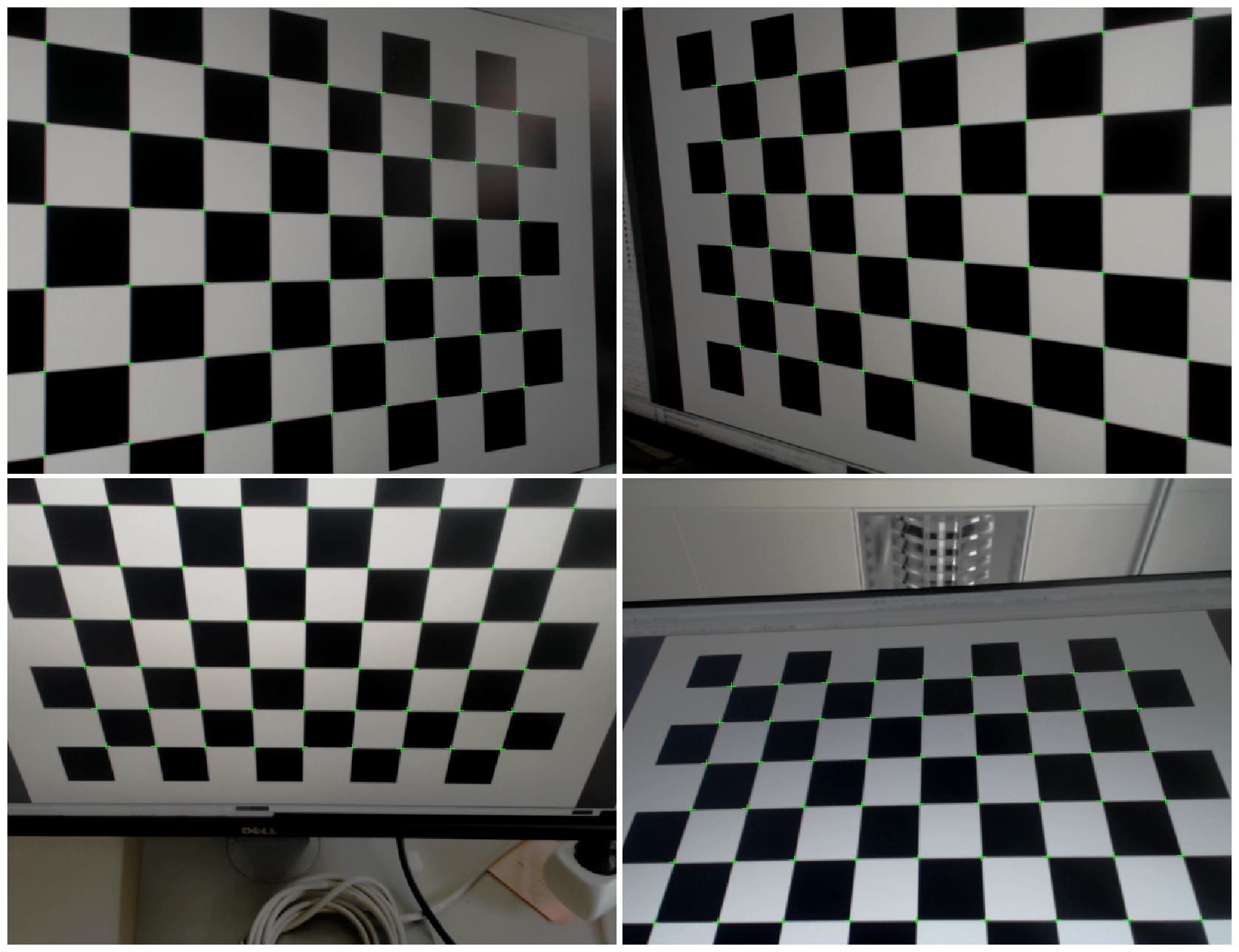
Figure_4: Samples of a good calibration sequence. The chessboard pattern covers a large part inside the images. There are chessboard corner measurements throughout the image, including corners and sides. The sequence contains slanted views of the pattern.
While recording the images, the pattern should be observed from various viewpoints. The camera can either be moved while holding the chessboard fixed or vice versa. During the movement you should observe how the chessboard appears in the captured images. The following points are important:
-
Relevant area for recognition: During recording, the inner area of the chessboard - as shown in Figure_3 - should always be visible. The chessboard will not be recognized if the case is not fulfilled. Those images will be ignored during calibration.
-
Distribution of measurements: Make sure that the chessboard appears as large as possible in the picture, not just clustered in the center of the image. This is necessary for the exact calculation of the distortion parameters. Corner measurements of the chessboard should be available in all image areas - especially near the edges of the image. Figure_5 shows examples that do not (!) allow a good calibration, as the detected chessboard covers only a small area in the center of the image. Figure_6 shows the result of such input data, i.e. the estimated distortion parameters are applied to undistorting an image. Only the image center is correctly equalized, the edges show overfitting effects due to a lack of measurements at image edges.
-
Oblique angles: For the exact calculation of the focal length and the center of the image, it is also important that the chessboard is taken from oblique angles. Recordings where the chessboard is always perpendicular to the camera direction (see Figure_7) do not allow accurate and reliable estimation of these parameters.
-
Slow and smooth movements: Most consumer cameras (including built-in cameras of mobile devices) have a rolling shutter, which means that the image from the camera sensor is sequentially read out. As a consequence, different pixels in the image will also be related to different time instants during the movement. In order to avoid negative effects on the calibration result, the chessboard (or the camera) should, if possible, be moved very slowly and quietly (no trembling movements).
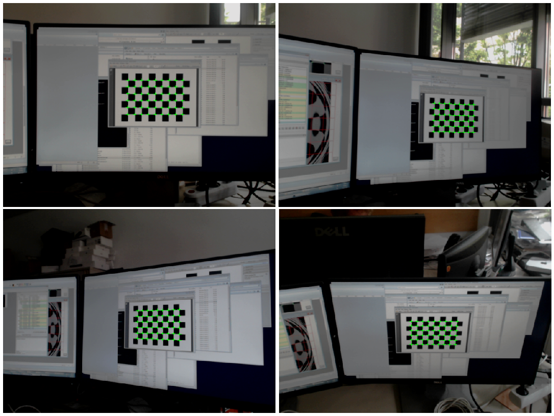
Figure_5: Example of unfavorable shots. The chessboard appears very small and only in the center of the image. This results in an unstable estimation of the distortion coefficients
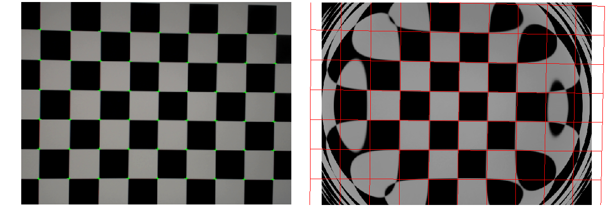
Figure_6: Undistorted results in the case where the measurements are all clustered in the image center during calibration. Undistorting the image on the left will reveal strong overfitting effects for the distortion coefficients (right). The red squares indicate where the chessboard edges should ideally appear after undistorting.
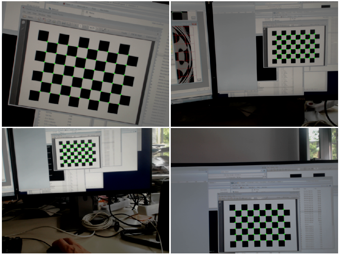
Figure_7: Another example of unfavorable shots. The camera view direction is always orthogonal to the chessboard pattern. This leads to an unstable estimate of the focal lengths and the principal point.