
documentation


In the prior article, we've made ourselves familiar with VisionLib Configuration files and introduced some of the parameters needed to set for tracking to work correctly – either manually in a text editor, or by using the tracking setup scene (which is recommended).
For better understanding, we distinguish between tracking parameters to influence the computer vision tracking, and parameters you need to configure, each time you setup a configuration to track a new object. Additionally, there are some parameters, which describe the general setup of your scene and thus influence the handling of the tracking result.
Initial parameters typically change per new configuration, whenever you are going to track a new object. You need to setup these parameters in the tracker.parameters {} element to get tracking started, and declare at least:
modelURI or models[]metricinitPoseSetting these will enable VisionLib to generate a so called Line Model, which is essential information used by the image processing during the tracking process.
| Name | Description | Examples |
|---|---|---|
modelURI | URI to your 3D file used as tracking reference | Relative to the .vl file: "modelURI": "project-dir:/my3Dmodel.obj" |
models | Alternative to modelURI: enables to load multiple 3D models as tracking reference, which are combined and treated as one single reference Line Model representation | "models":[ {"name":"Part1", "uri":"project-dir:/car-exterior.obj","enabled":"true" }, {"name":"Part2", "uri":"project-dir:/car-interior-.obj","enabled":"true" }] |
metric important | Sets the corresponding unit size of your model in metric scales (e.g mm, ft, m). This is an essential parameter which tremendously influences tracking quality | "metric": "m" |
initPose | Describes the initial pose or viewing angle, from which tracking should start. Essential for standard Model Tracking (excluding AutoInit and MultiModel Tracking setups) | "initPose": "t": [ x, y, z ], "r": [ x, y, z, w] } |
Using modelURI is rather straight-forward, and it is the very basic way to define the tracking target's reference by pointing to the corresponding 3D model used as reference.
There are other, more advanced ways to load 3D files for tracking, such as:
"models":[...] – uses an array, where a tracking target can be composed of multiple 3D files. These multiple files, however, will be treated like one single tracking reference, basically declared by (sub-)parts (it should not to be confused with Multi Model Tracking).TrackingAnchor to use Unity Hierarchy objects for tracking, which doesn't need a config file definition at all. Instead, the 3D meshes are handed over to VisionLib during runtime.Have a look at the example scenes at VisionLib Examples/Model Tracking/ModelLoading within the VisionLib.SDK.Examples-Unity.unitypackage for demos on how to load 3D models for tracking.
The metric assigns a real-world unit of measurement to the length units in your 3D model file. Set the metric such that the model dimensions, interpreted as the chosen metric, mirror the dimensions of the real object you intend to track. A mismatch between model and real object dimensions, caused by an incorrectly chosen metric, will lead to false tracking results.
Supported metric values: "mm", "cm", "dm", "m", "km", "in", "ft", "yd", "ch", "fur", "ml" If no metric is specified, VisionLib will default to using mm.
Using "m" (meters) is strongly recommended. See also "Which Metric Should I Use?" below.
Example: Say the (bounding box) dimensions of your 3D model file read:
If you set the metric parameter in the config file to "m" (meters), VisionLib will interpret this as:
It will consequently expect your physical object to be this size.
If your object was only 32 centimeters long, however, you would need to change Metric to "cm" (centimeters) instead:
If you are not sure about your model's metric, add the model as tracking geometry to a TrackingAnchor. The TrackingAnchor will then display the estimated size of the model.
As an alternative, you can use a 3D viewer such as MeshLab to find your model's dimensions in numerical units. Then compare these to the real object's dimensions. The metric is the unit of measurement you would have to assign to the model dimensions for them to match the real object's dimensions.
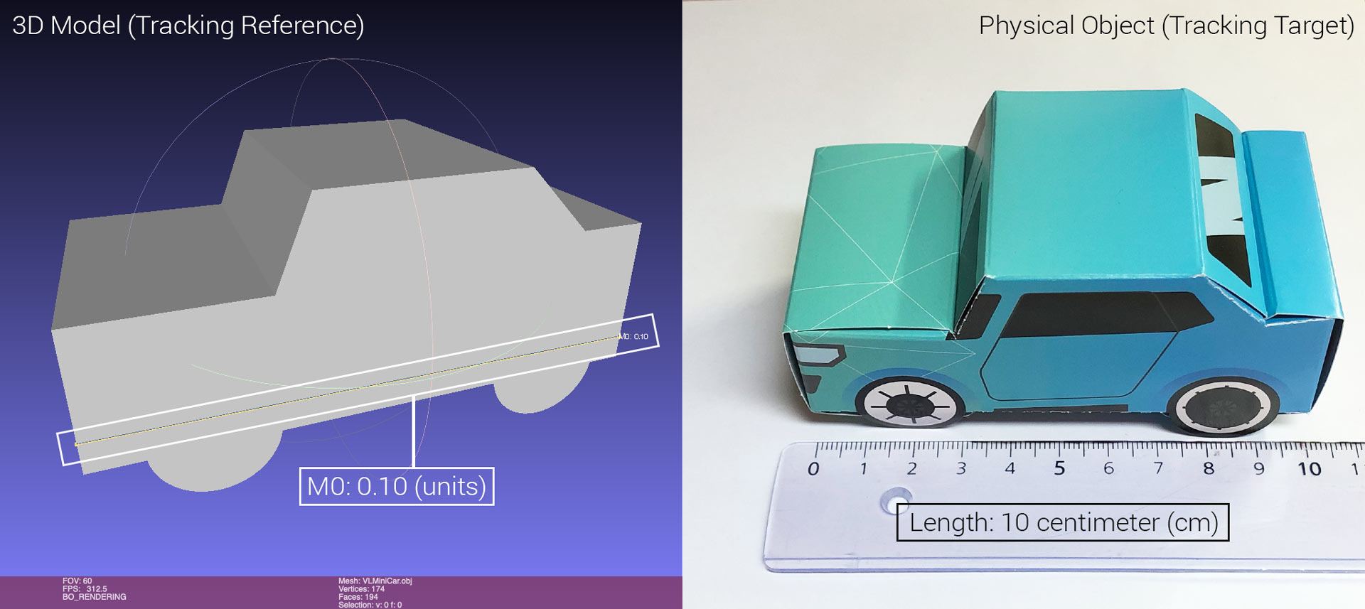
Take the DIY VisionLib Mini Car test object as an example (download the paper template & obj-file from our Resources page or get it from our Unity example scenes):
The length of our physical DIY car is 10 cm. Measuring the length of the corresponding .obj file in Meshlab shows 0.1 units. As 0.1 m = 10 cm, the correct metric for this model file is "m" (meters).
VisionLib also issues warnings, if it finds your 3D file's bounding box size implausible. This warning often indicates a metric mismatch.
We recommend to supply all meshes in meters. This sometimes requires adjusting the models in a 3D editor. While VisionLib can interpret different metrics, using meters becomes mandatory as soon as you use VisionLib tracking together with an external source for the camera movement (ARFoundation or HoloLens). These algorithms work in world coordinate systems defined in meters.
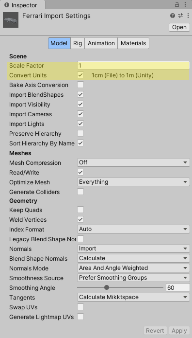
Some model formats already contain a metric for the model. Unity can interpret this metric when loading the model and transforms the file metric into the default Unity metric (which is meters). If this transformation isn't correct or you want to scale your model differently, you can also adjust the Scale Factor in the inspector view of the model file.
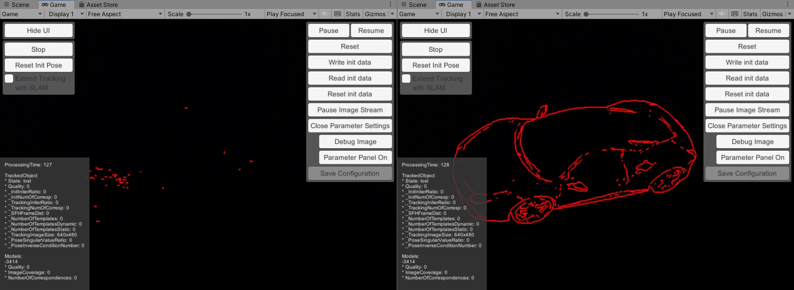
As stated above, the metric simply puts a real-world unit to the numerical units in a model file. Assume you have a 15.2 centimeters long object and a 3D model with mesh dimensions in the file reading 0.152 units. The correct metric would be "m" (meters), but you set it to "km" (kilometers).
VisionLib will interpret this as a 152 meter long object. Parameters, which depend on the metric (like the contour edge threshold/laplace threshold), will be influenced by this setting. The resulting line model will be extremely coarse and unfit for tracking a physical object that is, in fact, only 15.2 centimeters long. The image above illustrates this (left: incorrect metric, right: correct metric).
When using VisionLib with external SLAM (ARKit, ARCore, or HoloLens), using a wrong metric will also place the augmentation at a false position inside the scene. E.g. if the model is interpreted as a 152 meter long object, the augmentation will be placed very far away from the camera.
The init pose defines an initial camera pose (position and orientation) relative to the tracked object at which tracking can initialize. when working with Unity, you do not need to specify an init pose inside the configuration file. Instead, the init pose is the relative pose between a TrackingAnchor and its corresponding SLAM Camera GameObject in your scene.
Changing the tracking target requires adjustments to the init pose. This article explains the init pose and its adjustment in more detail.